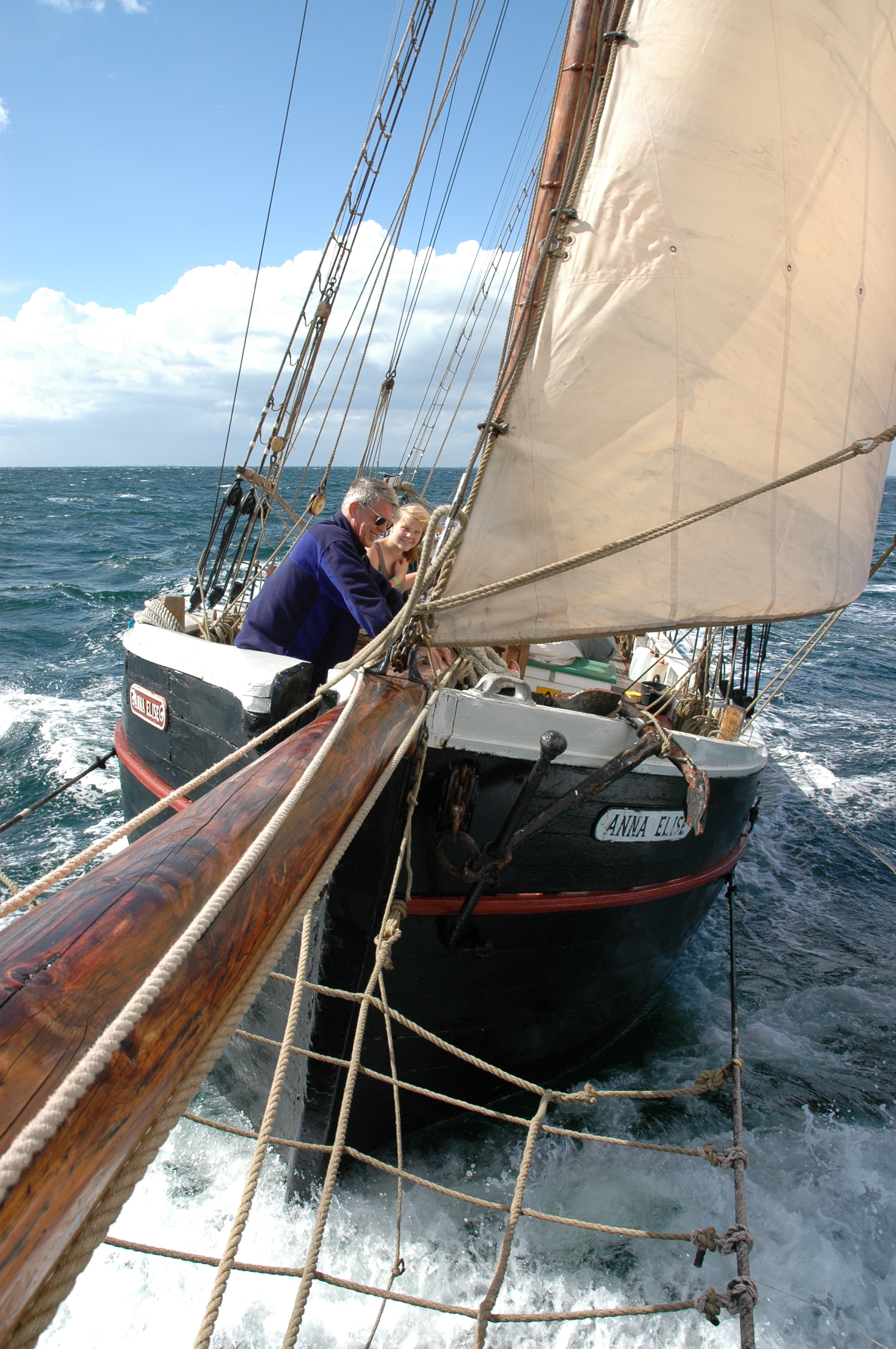
It has been more than a month since my last blog post, and you’d be forgiven for thinking that I’d lost interest in robots. It *is* true that I have been rather distracted by customers, including a trip to the USA. It is also holiday season, and I have been to a music festival. However, except for last week when I was skipper and this week when I am chillng out on the Anna Elise, the robot has been in my suitcase on every trip, and I have actually been working hard on it. I just haven’t been able to get anything new to work until very recently.
One problem was that robots do not travel particularly well. Put them in a suitcase every 3-4 days and bits quickly start falling off (if you have ever looked out the window of your plane and watched a baggage handling crew at work, that should be no surprise). I now have both 220v and 110v soldering irons (Thank You RadioShack!), and have so far been able to put humpty dumpty together again on arrival. But my last desperate attempt to collect some sonar data that I could publish before going sailing ended like this:
[embedplusvideo height=”356″ width=”584″ editlink=”http://bit.ly/161dKf0″ standard=”http://www.youtube.com/v/8LTOJzvk4YA?fs=1″ vars=”ytid=8LTOJzvk4YA&width=584&height=356&start=&stop=&rs=w&hd=0&autoplay=0&react=1&chapters=¬es=” id=”ep2156″ /]
Rewriting the Raspberry Pi – Arduino Comms Program
The BIG reason for the lack of visible progress is that I decided that the time had come to rewrite the control program for the Arduino. The robot uses a Raspberry Pi running Dyalog APL as the main “brain”, but because a high-level language on a Pi isn’t a “real time” programming environment, we are using an Arduino to control the I/O pins. The idea is that, by implementing a very simple “front-end processor” on the Arduino, we will have a tool that APL can control at a high level, leaving timing-dependent work like controlling pulse-width-modulated output pins, which need to be continuously updated, to the Arduino.
The old control program had a number of limitations; most importantly, it was only really possible to monitor a single input pin. This was good enough until the sonar was added to the infra-red sensor. The program also contained hard-coded information about how pins were being used. Finally, it was quite simply a badly-written piece of Arduino C, subject to intermittent timing-related glitches because the original authors were unaware of certain limitations of the Arduino.
So I decided to write about 5 pages of new C code, and it took me a month and a bit to get back to blogging. Apart from the distraction of having to pretend to still be the CTO of Dyalog Ltd, the real problem is that I am not (usually) a C programmer. C is a rather unforgiving language. Or rather, it is a VERY forgiving language – it allows you to write code that will compile without warnings but just not work, because you unwittingly asked it to do odd things like truncate the content of a variable that you have used in a context which assumes a shorter type (etc, etc, and etc).
To stack the odds further against me, the default Arduino environment has no real debugger. In addition, the I2C bus that we are using to communicate between the Pi and the Arduino is very timing-dependent, which means that any attempt to step through the code will necessarily cause it to fail. Even the standard Arduino practice of monitoring diagnostic messages written to the serial interface cannot be used as it alters the timing enough to cause many I2C requests to fail. So after 2-3 weeks of wailing and gnashing teeth, I implemented my own simple logging mechanism to return diagnostic info via I2C and finally managed to move very slowly forward and complete the new control program. And I even RTFM and a few web pages written by people who had done this kind of thing before – in particular, this post by Wayne Truchsess was extremely helpful.
I was hoping to be able to publish some results of using the new Sonar, but I tried to do this on a jet-lagged Sunday morning sandwiched between returning from the USA and heading off to sail, and absolutely everything I did went wrong. The batteries died in the middle of my data collection and, to make the day perfect, when I found a new set of batteries, a wheel fell off (see the video above)…so I won’t be able to blog about the sonar data until I am back from the sailing trip at the end of July. However, I would like to talk a bit about the new control program.
I2CArduinoComm v0.2
As previously mentioned, we have a piece or Arduino C code (available on GitHub), which supports a simple command language which APL on the Raspberry Pi uses to issue instructions to set or read I/O pin values. The BIG difference compared to the old version is that ALL code that either reads or sets pin values has been moved to the loop() function, which (if my understanding is correct) is dispatched by the Arduino “operating system” when the O/S is not busy with other tasks. The old program would read and update pins immediately upon receipt of I2C messages. The I2C bus is quite critical with respect to timing, and the old code was spending too much time reading pin values when a data request arrived – so we were missing the timing window for getting a response back in time – and possibly interfering with other timing-dependent activities on the Arduino. The new program constantly maintains arrays containing the latest input values (done in the “loop” function), so all an I2C read request needs to do is to transmit the current values.
Command Language Extensions
From a functional point of view, the main improvement is that the pin usage is completely configurable using a new “setup” command. At a lower level, the command language has been made more flexible. We no longer use a fixed command length; instead the first byte transmitted declares the length of the command (the first byte of all results is also the length of the response). The following commands are supported:
| Command Character |
Command Name | Description / Comments |
| I | Identify | Returns two bytes containing the major and minor version number of the ArdCom program (currently 0 2), followed by two bytes per defined pin (pin #, pin type). |
| R | Reset | Clears all pin definitions. |
| S | Setup | Declares pin types. Following the command character, triplets of (pin#, pin type, additional info) for each pin (see the pin type table below for details). “S” can be called several times in succession if the overall length of the command would otherwise exceed 32 bytes). |
| W | Write | Sets pin values: the command char is followed by pairs of (pin#, value). |
Pin Setup
Each pin declaration included in a setup command consists of a triplet of bytes, containing the pin#, type character, and “additional info”. Only the “p” pin type currently makes use of the additional info – for other pin types this value is ignored.
| Pin Type Character |
Type Name | Description / Comments |
| A | Analogue output | Uses the analogWrite function to set the value. |
| D | Digital output | Uses digitalWrite. |
| S | Servo output | Uses Servo.write to update the pin value. |
| a | Analogue input | Uses analogRead. |
| d | Digital input | Uses digitalRead. |
| p | Pulse input | Uses pulseIn to read a pulse-width modulated input. If “additional info” is set, then this should be a digital pin number which is given a 10ms HIGH signal to tell the device to provide an input pulse. |
See the Arduino Reference for descriptions of analogWrite, digitalWrite and the other functions mentioned above.
Reading Input Values
When an I2C read request is made (by APL on the Pi), the current values for all pins defined as inputs (in ascending order) are returned in a single transmission. The data stream contains two bytes (Most Significant Byte followed by LSB) for each input pin. If the control program wants to return diagnostic information, then the first data byte will have the value 254 and the rest of the transmission will be textual “log” data. 254 is an impossible value for the MSB of any input, because the maximum input value is 1023, which has an MSB value of 3. 254 was chosen rather than 255, which frequently occurs when there are transmission failures or other errors.
The ArdCom Class
A new APL class has been written to communicate with the new Arduino code. You can find the source code in the file ArdCom.dyalog in the GitHub repository. The DyaBot class has been updated to make use of the ArdCom encapsulation, the new version can be found in the Exampes folder in the repository. I will describe the in detail in my next blog post – probably not for another week, as the weather forecast looks superb for the next few days (probable route Faaborg-Aabenraa-Augustenborg-Gråsten-Flensburg-Sønderborg-Ærøskøbing).


