The official release of Dyalog APL for the Raspberry Pi now looks as if it going to happen on Friday! In preparation for this, we have been working on some examples to demonstrate things you can do on your Pi without a set of wheels attached – like making lights blink!
[embedplusvideo height=”356″ width=”584″ standard=”http://www.youtube.com/v/ztLIQgszE1s?fs=1″ vars=”ytid=ztLIQgszE1s&width=584&height=356&start=&stop=&rs=w&hd=0&autoplay=0&react=1&chapters=¬es=” id=”ep1275″ /]
Quick2Wire Interface Boards
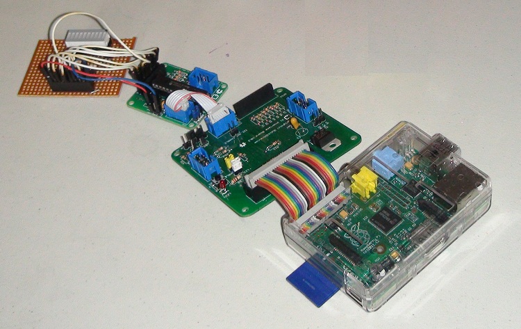
It is possible to connect input and output devices directly to your Pi. However, we have elected to do our experiments using the interface boards from Quick2Wire – to be precise the “Port Expander Combo“, which protects you from damaging your Pi by making wiring/soldering mistakes, and makes a number of interfaces more easily accessible. The photo below shows the LED bar used in the above video, attached to the combo:

The LED Pattern Generation Language (LEDPGL)
The Bar LED has 8 controllable LED’s. APL is actually a neat language for generating boolean patterns, for example:
      3↑1    ⍝ "3 take 1"
1 0 0
      8⍴3↑1 ⍝ "8 reshape 3 take 1"
1 0 0 1 0 0 1 0
      ¯1⌽8⍴3↑1 ⍝ "negative 1 rotate" of the above
0 1 0 0 1 0 0 1
      ⍪¯1 ¯2 ¯3⌽¨⊂8⍴3↑1 ⍝ "columnise the neg 1, 2 and 3 rotations..."
 0 1 0 0 1 0 0 1
 1 0 1 0 0 1 0 0
 0 1 0 1 0 0 1 0
Once you get into the habit of working with APL, you quickly learn to create small, functional “Embedded Domain Specific Notations” to work with your data. The LEDPGL namespace contains a small “pattern generation language”, which allows expressions like:
       LEDPGL.(0 4 shift 4 / 1 0)
 1 1 1 1 0 0 0 0   0 0 0 0 1 1 1 1
       LEDPGL.(show 0 4 shift 4 / 1 0)
 ⎕⎕⎕⎕....
 ....⎕⎕⎕⎕
Finally, the namespace contains a Demo function which takes a time interval in seconds as its argument (or 0 to use the “show” method to display the patterns in the session log). This is what was used to create the video at the top of this post:
       LEDPGL.Demo 0.1
 0 4 shift 4/1 0 ⍝ Left Right
 cycle 4 4/1 0   ⍝ Barber pole
 4 cycle 8 repeat head 4 ⍝ Ripple
 binary ⍳256             ⍝ Counter
 mirror cycle head 4     ⍝ Halves-in
 6 repeat 3 repeat x∨ reverse x←mirror cycle head 4 ⍝ Half-flip
 12 repeat ¯1↓x,1↓reverse x←mirror cycle head 4     ⍝ Out-In-Out
LED Morse Code
The Quick2wire expansion board (largest, closest board to the Pi in the first picture) has a single LED mounted, which can be controlled via GPIO. Our first example, which is included in the “Getting Started” guide which is included with Dyalog APL for the Pi – and available on GitHub – is an encoder for Morse Code. For example, the video below was generated by passing a character vector containing the only morse message that most people would be able to read:
GPIO.Morse 'SOS'[embedplusvideo height=”356″ width=”584″ standard=”http://www.youtube.com/v/xKBS0gtSDQ8?fs=1″ vars=”ytid=xKBS0gtSDQ8&width=584&height=356&start=&stop=&rs=w&hd=0&autoplay=0&react=1&chapters=¬es=” id=”ep7728″ /]


3 Responses
The set of lights is sufficient to implement a 1-d Game of Life. See: http://en.wikipedia.org/wiki/Elementary_cellular_automaton
Indeed it is – see https://www.dyalog.com/blog/2013/06/elementary-cellular-light-emitting-automaton/. Thanks a lot for pointing this out!